

Special Report
QNED Technology Maturity Analysis Report
₩6,000,000
June 22, 2021
Introduce
The reality of QNED (quantum dot nano-rod LED) that Samsung Display is preparing as a next-generation display has become clear.
As a result of analyzing 160 patents applied by Samsung Display, it was confirmed that the structure constituting the QNED has already been completed, and that the only remaining task is to keep the number of nano-rod LEDs arranged in the light-emitting pixel constant.
The number of aligned nano-rod LEDs per pixel, which determines the yield and image quality of QNED, is determined by the distribution of LEDs in the ink, the number of LEDs injected into the pixel, and the alignment ratio of the injected LEDs.
If the distribution of the number of nano-rod LEDs per pixel is different, there is a change in the voltage applied to each pixel, resulting in a defect.
It has been confirmed that Samsung Display has already developed a method for making the number of nano-rod LEDs per pixel constant and an algorithm that can make the luminance uniform even when the number of nano-rod LEDs is different.
In the “QNED Technology Maturity Analysis” published this time, the contents of the previous report published through analysis of 94 patents and 66 newly added patents were prepared. In addition, it has been analyzed and recorded in detail so that you can know what level Samsung Display’s QNED technology has reached.
In this report, the QNED patent number, classification table, and quantitative analysis data that have not been disclosed before are provided in Excel.
Contents
2.QNED Patent Analysis Result
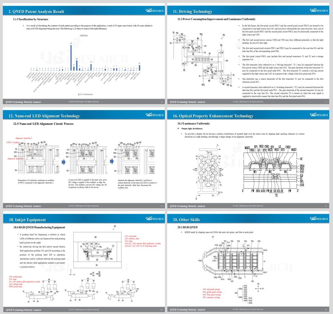
2.1 Classification by Structure
2.2 Classification by Purpose
3.What is QNED?
3.1 Nano-rod LED Basic Structure
3.2 QNED Structure
3.3 QNED Emitting Principle
3.4 Nano-rod LED Alignment Principle
3.5 Mother Glass Configuration
4.Nano-rod LED Manufacturing Process
5.Nano-rod LED Ink
5.1 Nano-rod LED Solvent
5.2 Dispersants
5.3 Photodegradable Functional Groups
6.QNED Manufacturing Process
6.1 TFT Manufacturing Process
6.2 Pixel Structure and Manufacturing Process
6.3 QD-CF Structure and Manufacturing Process
6.4 Panel Structure and Assembly Process
7.Bank and Pixel Wall Structure
7.1 Bank Structure and Role
7.2 Color Bank
7.3 Structure and Function of Pixel Wall
8.Structure of Insulation Layer and Insulation Pattern
8.1 Types and Roles of Insulation Layers
8.2 Alignment Functional Insulation Layer Type
8.3 Insulating Support
8.4 Insulation Pattern Thickness
8.5 Insulation Pattern Manufacturing Method
9.Electrode Type and Structure
9.1 Electrode Types
9.2 Pixel Electrode
9.3 Alignment Electrodes
9.4 Contact Electrode
9.5 Floating Electrodes
9.6 Reflecting Electrodes
10.Circuit Structure
10.1 Circuit for QNED
10.2 2T1C Structure
10.3 7T1C Structure
10.4 3T1C Structure
10.5 Wiring Circuits
11.Driving Technology
11.1 Low Gradation Driving Method
11.2 Gamma Correction
11.3 Power Consumption Improvement and Luminance Uniformity
11.4 Improvement of Luminous Efficiency
12.Nano-rod LED Alignment Technology
12.1 Nano-rod LED Alignment Elements
12.2 Nano-rod LED Ink and Alignment Process
12.3 Nano-rod LED Alignment Waveform
12.4 Nano-rod LED Alignment Circuit
12.5 Nano-rod LED Alignment Circuit Process
12.6 Nano-rod LED Alignment Circuit and Device Structure
13. Nano-rod LED Alignment Enhancement Technology
13.1 Circular Asymmetric Electrode Arrangement Structure
13.2 Shielding Electrodes
13.3 Floating Electrodes
13.4 Protruding Electrodes
13.5 Efficient Electrode Placement Structure
13.6 Different Electrode Widths
13.7 Connecting Alignment Line
13.8 Alignment Function Insulation Layer
13.9 Alignment by External Magnetic Fields
13.10 Alignment Using Surface Energy
14.Driving Technology for Nano-rod LED Alignment
14.1 Driving Technology for Alignment
14.2 Sensing Transistor for Alignment Status Check
14.3 Sensing Line
15.Improved Nano-rod LED Properties
15.1 Improvement of Light Output Efficiency
15.2 Nano-rod LED Orienter
15.3 Nano-rod LED Couplers
15.4 Protrusion Pattern Nano-rod LED
15.5 Conical Nano-rod LEDs
15.6 Asymmetric Nano-rod LEDs
15.7 Wavelength Conversion Material Coating
15.8 Preventing Nano-rod LED Damage
15.9 Short Prevention
16.Optical Property Enhancement Technology
16.1 Light Output Efficiency
16.2 Light Incident Efficiency
16.3 Luminance Uniformity
16.4 Visibility
16.5 Viewing Angle
16.6 Color Reproducibility
16.7 High Resolution
17.Defect Resolution Technology
17.1 Short Fault Prevention
17.2 Repair Transistor
17.3 Laser Repair
17.4 Conductive Patterns for Repair
17.5 Connection Pattern for Repair
17.6 Alignment Check and Rework
18.Inkjet Equipment
18.1 Inkjet Equipment Composition
18.2 Inkjet Printer Unit
18.3 Sensing Unit
18.4 Field Applied Module
18.5 Field Generating Units
18.6 RGB QNED Manufacturing Equipment
18.7 Inkjet Equipment for Orientation
19.7T2C TFT Structure and Process
19.1 7T2C TFT and Pixel Circuit Structure
19.2 7T2C TFT and Pixel Planar Structure
19.3 7T2C TFT and Pixel Cross Section Structure
19.4 7T2C TFT and Pixel Manufacturing Process
20.Other Skills
20.1 RGB QNED
20.2 Slim QNED
20.3 Bridge Pattern
20.4 Minimizing Contact Defects
20.5 Nano-rod Vertical Array Method
20.6 Quantum Rod Arrangement
20.7 Rubbing Techniques
20.8 Touch Sensor built-in QNED
21.Conclusion
21.1 QNED Success Factors
21.2 Technical Maturity
21.3 Defect Causes and Solutions
Report Sample
Previous Report Status
Related Products
-

QNED Technical Analysis Report
₩6,000,000November 12, 2020
This report consists of a detailed analysis of 94 patents filed by Samsung Display in relation to QNED, which were released by the second week of October 2020. In the first half of last year, QNED was analyzed as 41 patents, and there was a difference of about 6 months in the additional patents, but surprisingly technological progress was confirmed. The backplane of QNED is 7T2C TFT, and it was found that the oscillator for aligning the nano-rod LED and the transistor for repair are arranged together. The QNED circuit was configured similar to the TFT structure used in OLED for mobile devices. Since QNED is also a current driven device, it seems that precise control is required. Large OLED uses 3T1C structure.
-
QNED Structure and Manufacturing Technology Analysis Report
₩2,500,000May 25, 2020
UBI Research published a report analyzing Samsung Display’s 41 published patents for QNED (quantum dot nanorod LED). Samsung Display is developing QNED as the next-generation display business. Reports on the QNED structure have already been issued through various channels, but the substance of the QNED has not been released. This report contains directions for the development of QNED technology, including QNED pixel structure and nanorod LED alignment principles analyzed from published patent content. In addition, a manufacturing process constructed based on the structure depicted in the patent was included.
-
2026 Analysis Report on China’s OLED Supply Chain Management
₩0May 1, 2026
The newly published ‘2026 Analysis Report on China’s OLED Supply Chain Management’ is the first in the industry to organize, at a glance, the customer landscape and business stage of a wide range of OLED materials, components, and equipment companies in China. It is expected to serve as a practical guideline for global companies seeking to enter China’s steadily expanding OLED market.
The way panel makers build and maintain their supply chain management is a key determinant of their technological competitiveness. SCM is critically important not only for panel manufacturers, but also for materials, components, and equipment suppliers. To succeed in business, companies must clearly understand who their customers are, who their competitors are, and, for new entrants, how the existing market structure is already laid out.
There is a common denominator behind Samsung Display’s position as the global leader in panel technology and Apple’s strong leadership in the OLED smartphone business: SCM. The biggest reason Chinese panel makers and set manufacturers have not been able to scale as rapidly in OLED as they did in LCD is the supply chain. It is not possible to free-ride on the SCM networks that Samsung Display and Apple have already built.